As you can probably imagine, we get tips on a lot of really interesting projects here at Hackaday. Most are pretty serious, at least insofar as they aim to solve a specific problem in some new and clever way. Some, though, are a little more lighthearted, such as a fun project that came across the tips line back in May. Charmingly dubbed “pISSStream,” the project taps into NASA’s official public telemetry stream for the International Space Station to display the current level of the urine tank on the Space Station.
Now, there are a couple of reactions to a project like this when it comes across your desk. First and foremost is bemusement that someone would spend time and effort on a project like this — not that we don’t appreciate it; the icons alone are worth the price of admission. Next is sheer amazement that NASA provides access to a parameter like this in its public API, with a close second being the temptation to look at what other cool endpoints they expose.
But for my part, the first thing I thought of when I saw that project was, “How do they even measure liquid levels in space?” In a place where up and down don’t really have any practical meaning, the engineering challenges of liquid measurement must be pretty interesting. That led me down the rabbit hole of low-gravity process engineering, a field that takes everything you know about how fluids behave and flushes it into the space toilet.
What’s Up?
Before even considering the methods used to measure liquid levels in space, you really have to do away with the concept of “levels.” That’s tough to do for anyone who has spent a lifetime at the bottom of a gravity well, a place where the gravity vector is always straight down at 1 g, fluids always seek their own level, and the densest stuff eventually makes its way to the bottom of a container. None of this applies in space, a place where surface tension and capillary action take the lead role in determining how fluids behave.
We’ve all seen clips of astronauts aboard the Space Shuttle or ISS having fun playing with a bit of water liberated from a drinking pouch, floating in a wobbly spheroid until it gets sucked up with a straw. That’s surface tension in action, forcing the liquid to assume the minimum surface area for a given volume. In the absence of an acceleration vector, fluids will do exactly the same thing inside a tank on a spacecraft. In the Apollo days, NASA used cameras inside the fuel tanks of their Saturn rockets to understand fluid flow during flights. These films showed the fuel level rapidly decreasing while the engines were burning, but the remaining fuel rushing to fill the entire tank with individual blobs of floating liquid once in free-fall. SpaceX does the same today with their rockets, with equally impressive results — apologies for the soundtrack.
So, getting propellants to the outlets of tanks in rockets turns out to be not much of a chore, at least for boosters, since the acceleration vector is almost always directed toward the nominal bottom of the tank, where the outlets are located. For non-reusable stages, it doesn’t really matter if the remaining fuel floats around once the engines turn off, since it and the booster are just going to burn up upon reentry or end up at the bottom of the ocean. But for reusable boosters, or for rockets that need to be restarted after a period of free fall, the fuel and oxidizer need to be settled back into their tanks before the engines can use them again.
Ullage Motors, Bookkeeping, and Going With The Flow

Settling propellants requires at least a little acceleration in the right direction, which is provided by dedicated ullage motors. In general, ullage refers to the empty space in a closed container, and ullage motors are used to consolidate the mix of gas and liquid in a tank into a single volume. On the Saturn V rockets of the Apollo era, for example, up to a dozen solid-fuel ullage motors on the two upper stages were used to settle propellants.
With all the effort that goes into forcing liquid propellants to the bottom of their tanks, at least for most of the time, you’d think it would be pretty simple to include some sort of level gauging sensor, such as an ultrasonic sensor at the nominal top of the tank to measure the distance to the rapidly receding liquid surface as the engines burn. But in practice, there’s little need for sensing the volume of propellants left in the tank. Rather, the fuel remaining in the tank can be inferred from flow sensors in lines feeding the engines. If you know the flow rate and the starting volume, it’s easy enough to calculate the fuel remaining. SpaceX seems to use this method for their boosters, although they don’t expose a lot of detail to the public on their rocket designs. For the Saturn S-1C, the first stage of the Saturn V rocket, it was even simpler — they just filled the tanks with a known volume of propellants and burned them until they were basically empty.
In general, this is known as the bookkeeping or flow accounting method. This method has the disadvantage of compounding errors in flow measurement over time, but it’s still good enough for applications where some engineering wiggle room can be built in. In fact, this is the method used to monitor the urine tank level in the ISS, except in reverse. When the tank is emptied during resupply missions, the volume resets to zero, and each operation of one of the three Waste & Hygiene Compartments (WHC) aboard the station results in approximately 350 ml to 450 ml of fluid — urine, some flush water, and a small amount of liquid pretreatment — flowing into the urine holding tank. By keeping track of the number of flushes and by measuring the outflow of pretreated urine to the Urine Processing Assembly (UPA), which recycles the urine into potable water, the level of the tank can be estimated.
PUGS In Space
Monitoring pee on a space station may be important, but keeping track of propellants during crewed flights is a matter of life or death. During the Apollo missions, a variety of gauging methods were employed for fuel and oxidizer measurements, most of which relied on capacitance probes inside the tanks. The Apollo service module’s propulsion system used the Propellant Utilization Gauging Subsystem, or PUGS, to keep track of the fuel and oxidizer levels onboard.
PUGS relied primarily on capacitive probes mounted axially within the tank. For the fuel tanks, the sensor was a sealed Pyrex tube with a silver coating on the inside. The glass acted as the dielectric between the silver coating and the conductive Aerozine 50 fuel. In the oxidizer tanks, the inhibited nitrogen tetroxide acted as the dielectric, filling the space between concentric electrodes. Once settled with an ullage burn, the level of propellants could be determined by measuring the capacitance across the probes, which would vary with liquid level. Each probe also had a series of point contacts along its length. Measuring the impedance across the contacts would show which points were covered by propellant and which weren’t, giving a lower-resolution reading as a backup to the primary capacitive sensors.
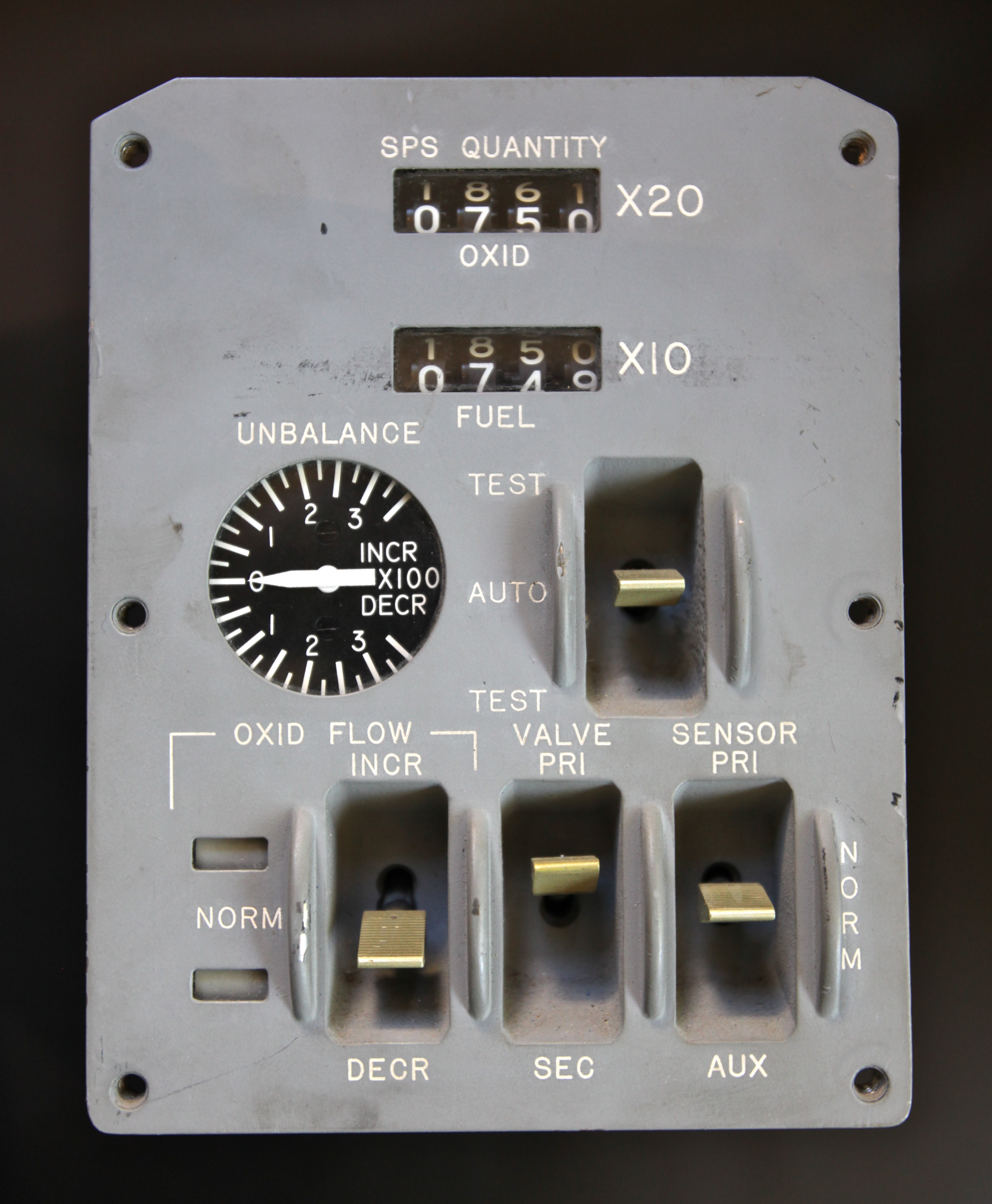
For the Lunar Module, propellant levels for the descent stage were monitored with a similar but simpler Propellant Quantity Gage System (PQGS). Except for an initial ullage burn, fuel settling wasn’t needed during descent thanks to lunar gravity. The LM also used the same propellants as the service module, so the PQGS capacitive probes were the same as the PUGS probes, except for the lack of auxiliary impedance-based sensors. The PQGS capacitive readings were used to calculate the percent of fuel and oxidizer remaining, which was displayed digitally on the LM control panel.
The PQGS probe on the early Apollo landings gave incorrect readings of the remaining propellants thanks to sloshing inside the tanks, a defect that was made famous by Mission Control’s heart-stopping callouts of how many seconds of fuel were left during the Apollo 11 landing. This was fixed after Apollo 12 by adding new anti-slosh baffles to the PQGS probes.
Counting Bubbles
For crewed flights, ullage burns to settle fuel and get accurate tank level measurements are easy to justify. But not so for satellites and deep-space probes, which are lofted into orbit at great expense. These spacecraft can only carry a limited amount of propellant for maneuvering and station-keeping, which has to last months or even years, and the idea of wasting any of that precious allotment on ullage is a non-starter.
To work around this, engineers have devised clever methods to estimate the amount of propellants or other liquids in tanks under microgravity conditions. The pressure-volume-temperature (PVT) method can estimate the volume of fluid remaining based on measurements from pressure and temperature sensors inside the tank and the ideal gas law. Like the flow accounting method, the accuracy of the PVT method tends to decrease over time, mainly because the resolution of pressure sensors tends to get worse as the pressure decreases.
For some fluids, the thermal gauging method might be employed. This is a variation of the PVT method, which involves applying heat to the tank while monitoring the pressure and temperature of its contents. If the thermal characteristics of the process fluid are well known, it’s possible to infer the volume remaining. The downside is that a good thermal model of the tank and its environment is needed; it wouldn’t do, for instance, to have unaccounted heat gain from solar radiation during a measurement, or loss of heat due to conduction to space via the structure of the spacecraft.
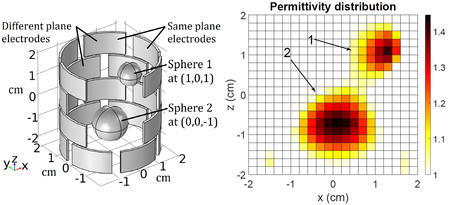
For better accuracy, a more recent development in microgravity tank gauging is electrical capacitance volume sensing (ECVS), and the closely related electrical capacitance volume tomography (ECVT). The two methods use arrays of electrodes on the inside surface of a tank. The mixed-phase fluid in the tank acts as a dielectric, allowing capacitance measurements between any pair of electrodes. Readings are collected across each combination of electrodes, which can be used to build a map of where fluid is located within the tank. This is especially useful for tanks where liquid is floating in discrete spheroids. The volume of each of these blobs can be calculated and totalled to give the amount of liquid in the tank.
One promising gauging method, especially for deep-space missions, is radio frequency mass gauging, or RFMG. This method uses a small antenna to inject RF signals into a tank. The liquid inside the tank reflects these signals; analyzing the spectrum of these reflections can be used to calculate the amount of liquid inside the tank. RFMG was tested on the ISS before heading to the Moon aboard Intuitive Machines’ IM-1 lander, which touched down softly on the lunar surface in February of 2024, only to tip over onto its side. Luckily, the RFMG system had nothing to do with the landing anomaly; in fact, the sensor was critical to determining that cryogenic fuel levels in the lander were correct when temperature sensors indicated the tank was colder than expected, potentially pointing to a leak.
Source link


